Both electrical and software synchronization are required. See below for detailed instructions.
Electrical Wiring Guide
- Leader-Follower Mode
- Follower-Only Mode (External Clock)
Overview
This mode is designed for configurations not using an External Clock Signal.You will utilize one camera inleader mode (outputting a synchronization signal) and all remaining cameras in follower mode.Leader/Follower Firmware Guide
Click here to see our guide on updating your camera between Leader and Follower modes.


Wiring

Example
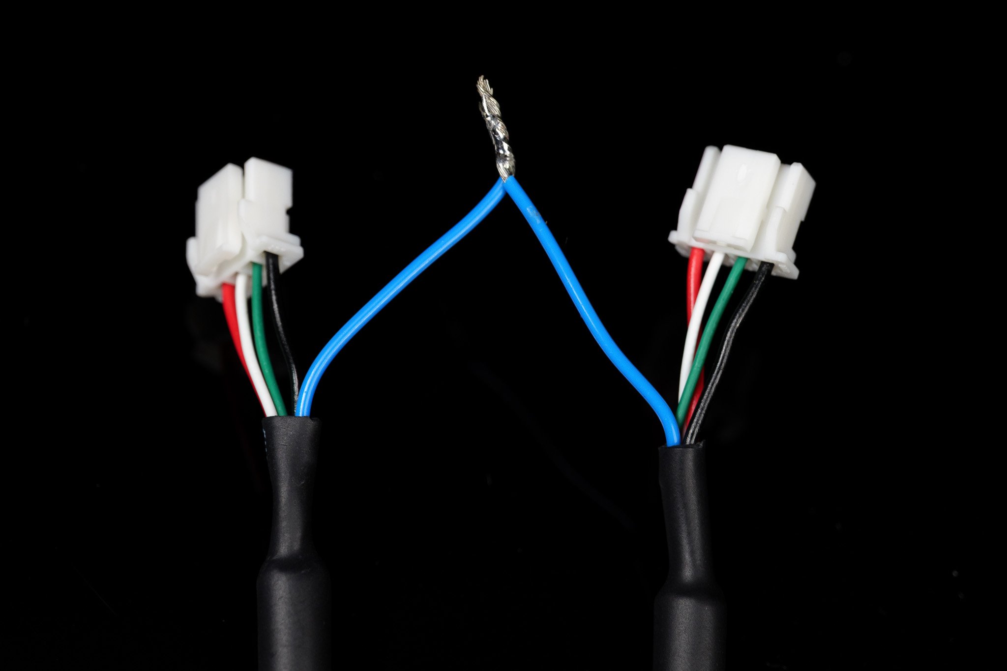
An example of wires from two cameras connected for frame-synchronization.


Synchronized Video Python Library (Linux)
In addition to our upcoming SDK, we currently provide a simple Python process to grab synchronized frames from your camera setups. (Note: This may be phased out in favor of the fully featured SDK in the future.)Synchronized Video Python Library
Follow our GitHub guide to install and use our custom Linux, python library.
Synchronized Stitched Video
This will go over using GStreamer to synchronize and stitch two video feeds. Then, creating a virtual device to use in other programs.- Linux
1
Install Required Packages
Install the necessary dependencies using the following command:
2
List Current Camera Devices
Run the following command to find your connected cameras:Example output:
3
Create a Virtual Device
Identify the device IDs of the two cameras you wish to use, then select a device ID number that is not currently listed.In this example, we will use
9 (as it is unused above) to create a virtual device named stellarHD_stitched. Update the 9 in the command below to match your chosen unused ID:4
Launch the GStreamer Pipeline
Launch the pipeline to create the stitched video and output the stream to your new virtual device:
You must keep this command running while using the synchronized, stitched videos. You can modify this command to add more cameras, change resolutions/framerates, or alter the layout.
5
Use the Virtual Device in OpenCV
OpenCV Starter Code
Follow our sample code to use
/dev/video9 in OpenCV.6
Remove the Loopback Device
To safely remove the loopback device, you can either restart your computer or run the following sequence of commands:1. Identify programs currently using the loopback device:2. Kill the processes using their PID (Process ID) numbers:3. Remove the loopback device: