Before soldering the wires to the provided USB connector, please ensure the following tasks have been completed:
- Cable is properly waterproofed, following the steps in the previous page.
- Cable penetrator has the o-ring in the o-ring groove.
- Cable penetrator is on the outer portion of the electronic housing end cap.
- The wires have been passed through the nut for the cable penetrator.
- The nut is on the inner portion of the electronic housing end cap.
Ensure the cable jacket is stripped back far enough for your application.
Recommended Cable Jacket Stripper
3/16” to 1 1/8” Diameter - Cable Strip & Ring Tool
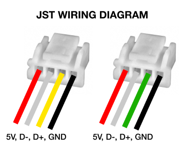
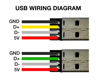
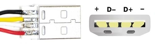
Ensure you are knowledgeable on the function of each wire.
- Black: Ground
- Red: 5V
- Yellow/Green: D+ (Data Positive)
- White: D- (Data Negative)
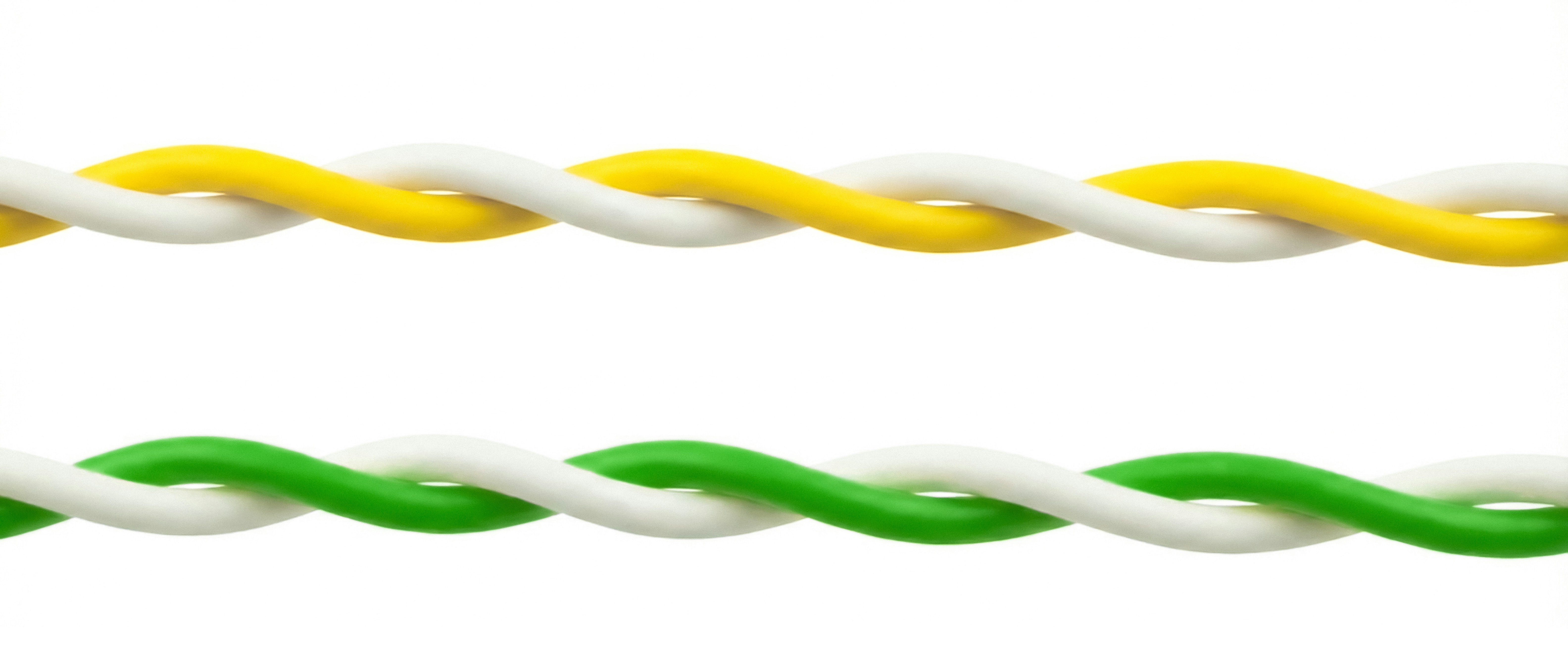
Ensure the next two wires are twisted/intertwined. Twisted pairs ensures the data signal is strong.