> ## Documentation Index
> Fetch the complete documentation index at: https://docs.dwe.ai/llms.txt
> Use this file to discover all available pages before exploring further.
# Frame-Synchronizing Multiple Cameras
> A guide on how to synchronize stellarHD cameras.
***This documentation is still being improved and under construction!***
Both **electrical** and **software** synchronization are required. See below for detailed instructions.
# Electrical Wiring Guide
## Overview
This mode is designed for configurations **not using an External Clock Signal**.
You will utilize one camera in `leader` mode (outputting a synchronization signal) and all remaining cameras in `follower` mode.
Click here to see our guide on updating your camera between Leader and Follower modes.

 ***
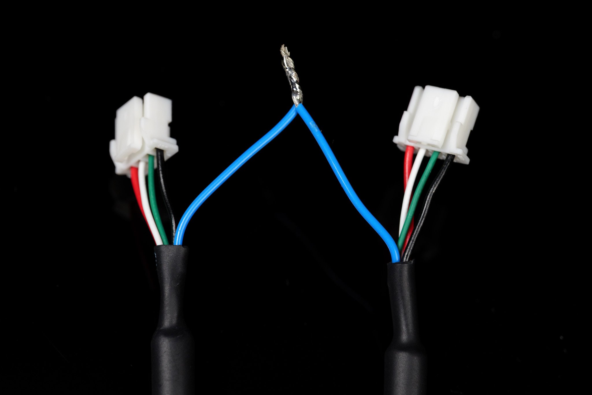
## Wiring
***
## Wiring
 ### Example
 ## Overview
This mode is designed for configurations **using an External Clock Signal** to output the synchronization signal for all cameras.
In this mode, all cameras must be set to `follower` mode.
Click here to see our guide on updating your camera between Leader and Follower modes.
## Overview
This mode is designed for configurations **using an External Clock Signal** to output the synchronization signal for all cameras.
In this mode, all cameras must be set to `follower` mode.
Click here to see our guide on updating your camera between Leader and Follower modes.

 ***
## Wiring
Check your specific device's product page for external frame-syncing specifications.
***
## Wiring
Check your specific device's product page for external frame-syncing specifications.
 ***
## External Clock Signal Generation
### Arduino Integration
The **Arduino Uno (ATmega328P)** is currently the only *confirmed* working board for this configuration.
Download the source code for the PWM library here: [ArduinoPWM v1.0.0](https://github.com/DeepWaterExploration/ArduinoPWM/archive/refs/tags/v1.0.0.zip)
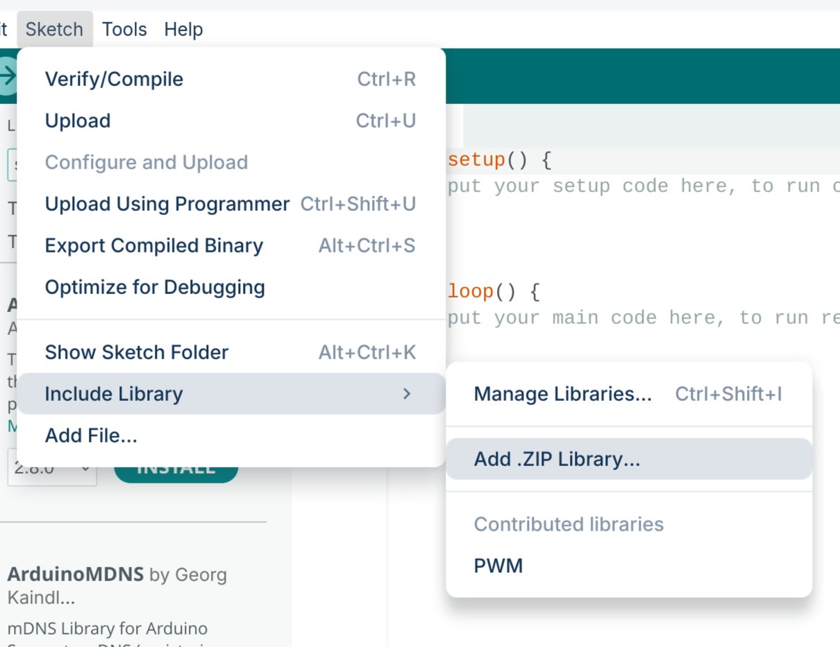
Import the downloaded `.ZIP` library into your Arduino IDE.
***
## External Clock Signal Generation
### Arduino Integration
The **Arduino Uno (ATmega328P)** is currently the only *confirmed* working board for this configuration.
Download the source code for the PWM library here: [ArduinoPWM v1.0.0](https://github.com/DeepWaterExploration/ArduinoPWM/archive/refs/tags/v1.0.0.zip)
Import the downloaded `.ZIP` library into your Arduino IDE.
 Upload one of the two sketches below to your Arduino.
* **Simple Control:** The quickest way to get started, but requires reflashing the firmware to adjust your FPS.
* **Serial Control:** Allows you to adjust frequency and duty cycle in real-time without reflashing (settings will reset if the device loses power).
```cpp theme={null}
#include
// Pin configuration
int pin = 9; // Pin
int value = 127; // Initial value for the PWM duty cycle
// SET FREQUENCY HERE
float frequency = 60; // Initial frequency in Hz
void setup()
{
// Initialize all timers except for timer0 to save timekeeping tasks
InitTimersSafe();
// Set the initial PWM frequency and duty cycle
if (SetPinFrequencySafe(pin, frequency))
{
pwmWrite(pin, value);
Serial.println("PWM frequency and initial duty cycle set.");
}
else
{
Serial.println("Failed to set frequency.");
}
}
```
```cpp theme={null}
#include
// Pin configuration
int pin = 9; // Pin
int value = 127; // Initial value for the PWM duty cycle
float frequency = 60; // Initial frequency in Hz
void setup()
{
Serial.begin(9600);
// Initialize all timers except for timer0 to save timekeeping tasks
InitTimersSafe();
// Set the initial PWM frequency and duty cycle
if (SetPinFrequencySafe(pin, frequency))
{
pwmWrite(pin, value);
Serial.println("PWM frequency and initial duty cycle set.");
}
else
{
Serial.println("Failed to set frequency.");
}
}
void loop()
{
if (Serial.available())
{
// Read frequency and duty cycle values over Serial
String inputString = Serial.readStringUntil('\n');
inputString.trim();
int freqDutySplitIndex = inputString.indexOf(',');
if (freqDutySplitIndex != -1)
{
String freqStr = inputString.substring(0, freqDutySplitIndex);
String dutyStr = inputString.substring(freqDutySplitIndex + 1);
// Parse floats
float newFrequency = freqStr.toFloat();
int newDutyCycle = dutyStr.toInt();
// Validate frequency range
if (newFrequency >= 1 && newFrequency <= 2000000)
{
// Set the PWM frequency and apply duty cycle
if (SetPinFrequencySafe(pin, newFrequency))
{
value = map(constrain(newDutyCycle, 0, 100), 0, 100, 0, 255);
pwmWrite(pin, value);
Serial.print("Set frequency to: ");
Serial.print(newFrequency);
Serial.print(" Hz, duty cycle to: ");
Serial.print(newDutyCycle);
Serial.println("%");
}
else
{
Serial.println("Failed to set new frequency.");
}
}
else
{
Serial.println("Invalid frequency value.");
}
}
else
{
Serial.println("Invalid input format. Use frequency,dutycycle (e.g., 60,50).");
}
}
}
```
This code allows you to modify the PWM signal on the fly. Open your serial monitor at `9600` baud and send commands using the format `{FREQUENCY},{DUTY_CYCLE}` (e.g., `60,50` for 60Hz at a 50% duty cycle).
***
## Synchronized Video Python Library (Linux)
In addition to our upcoming SDK, we currently provide a simple Python process to grab synchronized frames from your camera setups. *(Note: This may be phased out in favor of the fully featured SDK in the future.)*
Follow our GitHub guide to install and use our custom Linux, python library.
***
## Synchronized Stitched Video
This will go over using GStreamer to synchronize and stitch two video feeds.
Then, creating a virtual device to use in other programs.
Install the necessary dependencies using the following command:
```bash theme={null}
sudo apt install -y libx264-dev libjpeg-dev \
libglib2.0-dev libgstreamer1.0-dev libgstreamer-plugins-base1.0-dev \
gstreamer1.0-tools gstreamer1.0-x gstreamer1.0-plugins-base gstreamer1.0-plugins-good \
gstreamer1.0-plugins-bad gstreamer1.0-libav libgstreamer-plugins-bad1.0-dev \
gstreamer1.0-plugins-ugly gstreamer1.0-gl \
v4l-utils
```
Run the following command to find your connected cameras:
```bash theme={null}
v4l2-ctl --list-devices
```
**Example output:**
```text theme={null}
stellarHD Leader: stellarHD Lea (usb-0000:00:14.0-8.3):
/dev/video0
/dev/video1
/dev/media0
stellarHD Follower: stellarHD F (usb-0000:00:14.0-8.4):
/dev/video2
/dev/video3
/dev/media1
```
Identify the device IDs of the two cameras you wish to use, then select a device ID number that is **not** currently listed.
In this example, we will use `9` (as it is unused above) to create a virtual device named `stellarHD_stitched`. Update the `9` in the command below to match your chosen unused ID:
```bash theme={null}
sudo modprobe v4l2loopback video_nr=9 \
card_label=stellarHD_stitched exclusive_caps=1
```
Launch the pipeline to create the stitched video and output the stream to your new virtual device:
```bash theme={null}
gst-launch-1.0 -v \
compositor name=mix \
sink_0::xpos=0 sink_0::ypos=0 sink_0::alpha=1 \
sink_1::xpos=1600 sink_1::ypos=0 sink_1::alpha=1 \
! jpegenc ! jpegdec ! videoconvert ! v4l2sink device=/dev/video9 \
v4l2src device=/dev/video0 ! image/jpeg,width=1600,framerate=60/1 ! jpegdec ! videorate ! mix.sink_0 \
v4l2src device=/dev/video2 ! image/jpeg,width=1600,framerate=60/1 ! jpegdec ! videorate ! mix.sink_1
```
You must keep this command running while using the synchronized, stitched videos. You can modify this command to add more cameras, change resolutions/framerates, or alter the layout.
Follow our sample code to use `/dev/video9` in OpenCV.
To safely remove the loopback device, you can either restart your computer or run the following sequence of commands:
**1. Identify programs currently using the loopback device:**
```bash theme={null}
sudo lsof /dev/video*
```
**2. Kill the processes using their PID (Process ID) numbers:**
```bash theme={null}
sudo kill
```
**3. Remove the loopback device:**
```bash theme={null}
sudo modprobe -r v4l2loopback
```
Upload one of the two sketches below to your Arduino.
* **Simple Control:** The quickest way to get started, but requires reflashing the firmware to adjust your FPS.
* **Serial Control:** Allows you to adjust frequency and duty cycle in real-time without reflashing (settings will reset if the device loses power).
```cpp theme={null}
#include
// Pin configuration
int pin = 9; // Pin
int value = 127; // Initial value for the PWM duty cycle
// SET FREQUENCY HERE
float frequency = 60; // Initial frequency in Hz
void setup()
{
// Initialize all timers except for timer0 to save timekeeping tasks
InitTimersSafe();
// Set the initial PWM frequency and duty cycle
if (SetPinFrequencySafe(pin, frequency))
{
pwmWrite(pin, value);
Serial.println("PWM frequency and initial duty cycle set.");
}
else
{
Serial.println("Failed to set frequency.");
}
}
```
```cpp theme={null}
#include
// Pin configuration
int pin = 9; // Pin
int value = 127; // Initial value for the PWM duty cycle
float frequency = 60; // Initial frequency in Hz
void setup()
{
Serial.begin(9600);
// Initialize all timers except for timer0 to save timekeeping tasks
InitTimersSafe();
// Set the initial PWM frequency and duty cycle
if (SetPinFrequencySafe(pin, frequency))
{
pwmWrite(pin, value);
Serial.println("PWM frequency and initial duty cycle set.");
}
else
{
Serial.println("Failed to set frequency.");
}
}
void loop()
{
if (Serial.available())
{
// Read frequency and duty cycle values over Serial
String inputString = Serial.readStringUntil('\n');
inputString.trim();
int freqDutySplitIndex = inputString.indexOf(',');
if (freqDutySplitIndex != -1)
{
String freqStr = inputString.substring(0, freqDutySplitIndex);
String dutyStr = inputString.substring(freqDutySplitIndex + 1);
// Parse floats
float newFrequency = freqStr.toFloat();
int newDutyCycle = dutyStr.toInt();
// Validate frequency range
if (newFrequency >= 1 && newFrequency <= 2000000)
{
// Set the PWM frequency and apply duty cycle
if (SetPinFrequencySafe(pin, newFrequency))
{
value = map(constrain(newDutyCycle, 0, 100), 0, 100, 0, 255);
pwmWrite(pin, value);
Serial.print("Set frequency to: ");
Serial.print(newFrequency);
Serial.print(" Hz, duty cycle to: ");
Serial.print(newDutyCycle);
Serial.println("%");
}
else
{
Serial.println("Failed to set new frequency.");
}
}
else
{
Serial.println("Invalid frequency value.");
}
}
else
{
Serial.println("Invalid input format. Use frequency,dutycycle (e.g., 60,50).");
}
}
}
```
This code allows you to modify the PWM signal on the fly. Open your serial monitor at `9600` baud and send commands using the format `{FREQUENCY},{DUTY_CYCLE}` (e.g., `60,50` for 60Hz at a 50% duty cycle).
***
## Synchronized Video Python Library (Linux)
In addition to our upcoming SDK, we currently provide a simple Python process to grab synchronized frames from your camera setups. *(Note: This may be phased out in favor of the fully featured SDK in the future.)*
Follow our GitHub guide to install and use our custom Linux, python library.
***
## Synchronized Stitched Video
This will go over using GStreamer to synchronize and stitch two video feeds.
Then, creating a virtual device to use in other programs.
Install the necessary dependencies using the following command:
```bash theme={null}
sudo apt install -y libx264-dev libjpeg-dev \
libglib2.0-dev libgstreamer1.0-dev libgstreamer-plugins-base1.0-dev \
gstreamer1.0-tools gstreamer1.0-x gstreamer1.0-plugins-base gstreamer1.0-plugins-good \
gstreamer1.0-plugins-bad gstreamer1.0-libav libgstreamer-plugins-bad1.0-dev \
gstreamer1.0-plugins-ugly gstreamer1.0-gl \
v4l-utils
```
Run the following command to find your connected cameras:
```bash theme={null}
v4l2-ctl --list-devices
```
**Example output:**
```text theme={null}
stellarHD Leader: stellarHD Lea (usb-0000:00:14.0-8.3):
/dev/video0
/dev/video1
/dev/media0
stellarHD Follower: stellarHD F (usb-0000:00:14.0-8.4):
/dev/video2
/dev/video3
/dev/media1
```
Identify the device IDs of the two cameras you wish to use, then select a device ID number that is **not** currently listed.
In this example, we will use `9` (as it is unused above) to create a virtual device named `stellarHD_stitched`. Update the `9` in the command below to match your chosen unused ID:
```bash theme={null}
sudo modprobe v4l2loopback video_nr=9 \
card_label=stellarHD_stitched exclusive_caps=1
```
Launch the pipeline to create the stitched video and output the stream to your new virtual device:
```bash theme={null}
gst-launch-1.0 -v \
compositor name=mix \
sink_0::xpos=0 sink_0::ypos=0 sink_0::alpha=1 \
sink_1::xpos=1600 sink_1::ypos=0 sink_1::alpha=1 \
! jpegenc ! jpegdec ! videoconvert ! v4l2sink device=/dev/video9 \
v4l2src device=/dev/video0 ! image/jpeg,width=1600,framerate=60/1 ! jpegdec ! videorate ! mix.sink_0 \
v4l2src device=/dev/video2 ! image/jpeg,width=1600,framerate=60/1 ! jpegdec ! videorate ! mix.sink_1
```
You must keep this command running while using the synchronized, stitched videos. You can modify this command to add more cameras, change resolutions/framerates, or alter the layout.
Follow our sample code to use `/dev/video9` in OpenCV.
To safely remove the loopback device, you can either restart your computer or run the following sequence of commands:
**1. Identify programs currently using the loopback device:**
```bash theme={null}
sudo lsof /dev/video*
```
**2. Kill the processes using their PID (Process ID) numbers:**
```bash theme={null}
sudo kill
```
**3. Remove the loopback device:**
```bash theme={null}
sudo modprobe -r v4l2loopback
```