> ## Documentation Index
> Fetch the complete documentation index at: https://docs.dwe.ai/llms.txt
> Use this file to discover all available pages before exploring further.
# 複数カメラのフレーム同期
> stellarHD カメラを同期する方法のガイドです。
***このドキュメントは現在改善中であり、作成中です!***
**電気的**および**ソフトウェア的**同期の両方が必要です。詳細な手順については以下を参照してください。
# 電気配線ガイド
## 概要
このモードは、**外部クロック信号を使用しない**構成向けに設計されています。
1 台のカメラを `leader` モード(同期信号を出力)で、残りのすべてのカメラを `follower` モードで使用します。
カメラを Leader モードと Follower モードの間で更新する方法のガイドはこちらをクリックしてください。

 ***
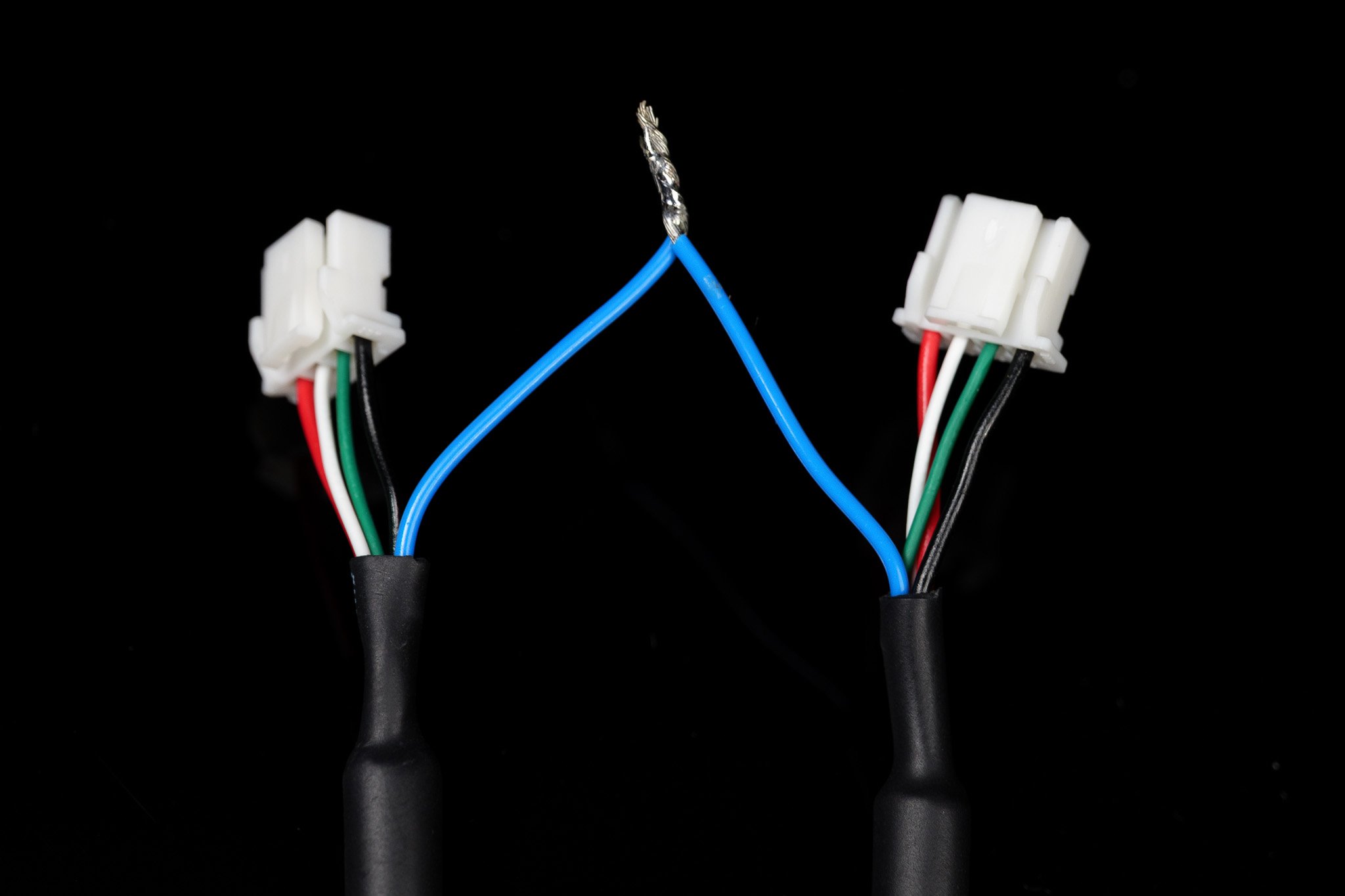
## 配線
***
## 配線
 ### 例
### 例
 ## 概要
このモードは、すべてのカメラに対して同期信号を出力するために**外部クロック信号を使用する**構成向けに設計されています。
このモードでは、すべてのカメラを `follower` モードに設定する必要があります。
カメラを Leader モードと Follower モードの間で更新する方法のガイドはこちらをクリックしてください。
## 概要
このモードは、すべてのカメラに対して同期信号を出力するために**外部クロック信号を使用する**構成向けに設計されています。
このモードでは、すべてのカメラを `follower` モードに設定する必要があります。
カメラを Leader モードと Follower モードの間で更新する方法のガイドはこちらをクリックしてください。

 ***
## 配線
外部フレーム同期仕様については、お使いの特定デバイスの製品ページを確認してください。
***
## 配線
外部フレーム同期仕様については、お使いの特定デバイスの製品ページを確認してください。
 ***
## 外部クロック信号の生成
### Arduino との統合
この構成で *確認済み* に動作するボードは、現時点では **Arduino Uno (ATmega328P)** のみです。
PWM ライブラリのソースコードはこちらからダウンロードしてください: [ArduinoPWM v1.0.0](https://github.com/DeepWaterExploration/ArduinoPWM/archive/refs/tags/v1.0.0.zip)
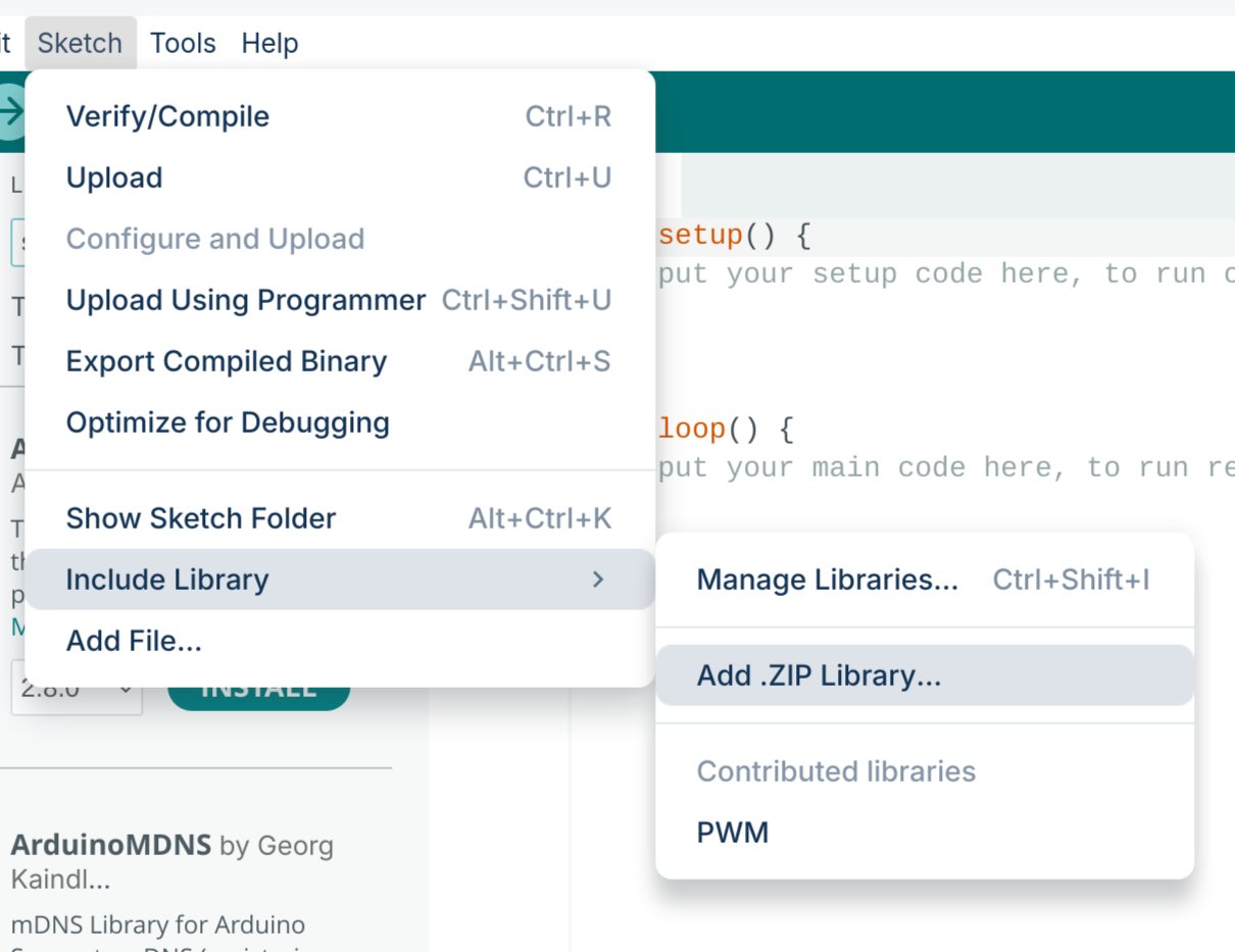
ダウンロードした `.ZIP` ライブラリを Arduino IDE にインポートします。
***
## 外部クロック信号の生成
### Arduino との統合
この構成で *確認済み* に動作するボードは、現時点では **Arduino Uno (ATmega328P)** のみです。
PWM ライブラリのソースコードはこちらからダウンロードしてください: [ArduinoPWM v1.0.0](https://github.com/DeepWaterExploration/ArduinoPWM/archive/refs/tags/v1.0.0.zip)
ダウンロードした `.ZIP` ライブラリを Arduino IDE にインポートします。
 以下の 2 つのスケッチのいずれかを Arduino にアップロードします。
* **シンプル制御:** 最も簡単に始められますが、FPS を調整するにはファームウェアを再書き込みする必要があります。
* **シリアル制御:** 再書き込みなしで周波数とデューティサイクルをリアルタイムで調整できます(デバイスの電源が切れると設定はリセットされます)。
```cpp theme={null}
#include
// ピン構成
int pin = 9; // ピン
int value = 127; // PWM デューティサイクルの初期値
// ここで周波数を設定
float frequency = 60; // 初期周波数(Hz)
void setup()
{
// 時間計測タスクを保護するため、timer0 以外のすべてのタイマーを初期化
InitTimersSafe();
// 初期 PWM 周波数とデューティサイクルを設定
if (SetPinFrequencySafe(pin, frequency))
{
pwmWrite(pin, value);
Serial.println("PWM frequency and initial duty cycle set.");
}
else
{
Serial.println("Failed to set frequency.");
}
}
```
```cpp theme={null}
#include
// ピン構成
int pin = 9; // ピン
int value = 127; // PWM デューティサイクルの初期値
float frequency = 60; // 初期周波数(Hz)
void setup()
{
Serial.begin(9600);
// 時間計測タスクを保護するため、timer0 以外のすべてのタイマーを初期化
InitTimersSafe();
// 初期 PWM 周波数とデューティサイクルを設定
if (SetPinFrequencySafe(pin, frequency))
{
pwmWrite(pin, value);
Serial.println("PWM frequency and initial duty cycle set.");
}
else
{
Serial.println("Failed to set frequency.");
}
}
void loop()
{
if (Serial.available())
{
// Serial から周波数とデューティサイクル値を読み取る
String inputString = Serial.readStringUntil('\n');
inputString.trim();
int freqDutySplitIndex = inputString.indexOf(',');
if (freqDutySplitIndex != -1)
{
String freqStr = inputString.substring(0, freqDutySplitIndex);
String dutyStr = inputString.substring(freqDutySplitIndex + 1);
// float をパース
float newFrequency = freqStr.toFloat();
int newDutyCycle = dutyStr.toInt();
// 周波数範囲を検証
if (newFrequency >= 1 && newFrequency <= 2000000)
{
// PWM 周波数を設定し、デューティサイクルを適用
if (SetPinFrequencySafe(pin, newFrequency))
{
value = map(constrain(newDutyCycle, 0, 100), 0, 100, 0, 255);
pwmWrite(pin, value);
Serial.print("Set frequency to: ");
Serial.print(newFrequency);
Serial.print(" Hz, duty cycle to: ");
Serial.print(newDutyCycle);
Serial.println("%");
}
else
{
Serial.println("Failed to set new frequency.");
}
}
else
{
Serial.println("Invalid frequency value.");
}
}
else
{
Serial.println("Invalid input format. Use frequency,dutycycle (e.g., 60,50).");
}
}
}
```
このコードを使用すると、PWM 信号をその場で変更できます。シリアルモニタを `9600` ボーで開き、`{FREQUENCY},{DUTY_CYCLE}` の形式でコマンドを送信します(例: 60Hz、デューティサイクル 50% の場合は `60,50`)。
***
## 同期ビデオ Python ライブラリ(Linux)
近日公開予定の SDK に加えて、現在、カメラセットアップから同期されたフレームを取得するためのシンプルな Python プロセスを提供しています。*(注意: これは将来的に、フル機能の SDK に置き換えられる場合があります。)*
GitHub ガイドに従って、当社のカスタム Linux Python ライブラリをインストールおよび使用してください。
***
## 同期されたスティッチビデオ
ここでは、GStreamer を使用して 2 つのビデオフィードを同期しスティッチする方法と、その後他のプログラムで使用するための仮想デバイスを作成する方法について説明します。
次のコマンドを使用して必要な依存関係をインストールします:
```bash theme={null}
sudo apt install -y libx264-dev libjpeg-dev \
libglib2.0-dev libgstreamer1.0-dev libgstreamer-plugins-base1.0-dev \
gstreamer1.0-tools gstreamer1.0-x gstreamer1.0-plugins-base gstreamer1.0-plugins-good \
gstreamer1.0-plugins-bad gstreamer1.0-libav libgstreamer-plugins-bad1.0-dev \
gstreamer1.0-plugins-ugly gstreamer1.0-gl \
v4l-utils
```
次のコマンドを実行して、接続されているカメラを確認します:
```bash theme={null}
v4l2-ctl --list-devices
```
**出力例:**
```text theme={null}
stellarHD Leader: stellarHD Lea (usb-0000:00:14.0-8.3):
/dev/video0
/dev/video1
/dev/media0
stellarHD Follower: stellarHD F (usb-0000:00:14.0-8.4):
/dev/video2
/dev/video3
/dev/media1
```
使用する 2 台のカメラのデバイス ID を特定し、現在リストに**ない**デバイス ID 番号を選択します。
この例では、`9`(上記で未使用)を使用して `stellarHD_stitched` という仮想デバイスを作成します。以下のコマンドの `9` を選択した未使用 ID に置き換えてください:
```bash theme={null}
sudo modprobe v4l2loopback video_nr=9 \
card_label=stellarHD_stitched exclusive_caps=1
```
スティッチビデオを作成し、ストリームを新しい仮想デバイスに出力するパイプラインを起動します:
```bash theme={null}
gst-launch-1.0 -v \
compositor name=mix \
sink_0::xpos=0 sink_0::ypos=0 sink_0::alpha=1 \
sink_1::xpos=1600 sink_1::ypos=0 sink_1::alpha=1 \
! jpegenc ! jpegdec ! videoconvert ! v4l2sink device=/dev/video9 \
v4l2src device=/dev/video0 ! image/jpeg,width=1600,framerate=60/1 ! jpegdec ! videorate ! mix.sink_0 \
v4l2src device=/dev/video2 ! image/jpeg,width=1600,framerate=60/1 ! jpegdec ! videorate ! mix.sink_1
```
同期したスティッチビデオを使用している間は、このコマンドを実行し続ける必要があります。このコマンドを変更して、カメラを追加したり、解像度/フレームレートを変更したり、レイアウトを変更したりできます。
サンプルコードに従って、OpenCV で `/dev/video9` を使用します。
ループバックデバイスを安全に削除するには、コンピューターを再起動するか、次のコマンドを順番に実行できます:
**1. 現在ループバックデバイスを使用しているプログラムを特定:**
```bash theme={null}
sudo lsof /dev/video*
```
**2. PID(プロセス ID)番号を使用してプロセスを終了:**
```bash theme={null}
sudo kill
```
**3. ループバックデバイスを削除:**
```bash theme={null}
sudo modprobe -r v4l2loopback
```
以下の 2 つのスケッチのいずれかを Arduino にアップロードします。
* **シンプル制御:** 最も簡単に始められますが、FPS を調整するにはファームウェアを再書き込みする必要があります。
* **シリアル制御:** 再書き込みなしで周波数とデューティサイクルをリアルタイムで調整できます(デバイスの電源が切れると設定はリセットされます)。
```cpp theme={null}
#include
// ピン構成
int pin = 9; // ピン
int value = 127; // PWM デューティサイクルの初期値
// ここで周波数を設定
float frequency = 60; // 初期周波数(Hz)
void setup()
{
// 時間計測タスクを保護するため、timer0 以外のすべてのタイマーを初期化
InitTimersSafe();
// 初期 PWM 周波数とデューティサイクルを設定
if (SetPinFrequencySafe(pin, frequency))
{
pwmWrite(pin, value);
Serial.println("PWM frequency and initial duty cycle set.");
}
else
{
Serial.println("Failed to set frequency.");
}
}
```
```cpp theme={null}
#include
// ピン構成
int pin = 9; // ピン
int value = 127; // PWM デューティサイクルの初期値
float frequency = 60; // 初期周波数(Hz)
void setup()
{
Serial.begin(9600);
// 時間計測タスクを保護するため、timer0 以外のすべてのタイマーを初期化
InitTimersSafe();
// 初期 PWM 周波数とデューティサイクルを設定
if (SetPinFrequencySafe(pin, frequency))
{
pwmWrite(pin, value);
Serial.println("PWM frequency and initial duty cycle set.");
}
else
{
Serial.println("Failed to set frequency.");
}
}
void loop()
{
if (Serial.available())
{
// Serial から周波数とデューティサイクル値を読み取る
String inputString = Serial.readStringUntil('\n');
inputString.trim();
int freqDutySplitIndex = inputString.indexOf(',');
if (freqDutySplitIndex != -1)
{
String freqStr = inputString.substring(0, freqDutySplitIndex);
String dutyStr = inputString.substring(freqDutySplitIndex + 1);
// float をパース
float newFrequency = freqStr.toFloat();
int newDutyCycle = dutyStr.toInt();
// 周波数範囲を検証
if (newFrequency >= 1 && newFrequency <= 2000000)
{
// PWM 周波数を設定し、デューティサイクルを適用
if (SetPinFrequencySafe(pin, newFrequency))
{
value = map(constrain(newDutyCycle, 0, 100), 0, 100, 0, 255);
pwmWrite(pin, value);
Serial.print("Set frequency to: ");
Serial.print(newFrequency);
Serial.print(" Hz, duty cycle to: ");
Serial.print(newDutyCycle);
Serial.println("%");
}
else
{
Serial.println("Failed to set new frequency.");
}
}
else
{
Serial.println("Invalid frequency value.");
}
}
else
{
Serial.println("Invalid input format. Use frequency,dutycycle (e.g., 60,50).");
}
}
}
```
このコードを使用すると、PWM 信号をその場で変更できます。シリアルモニタを `9600` ボーで開き、`{FREQUENCY},{DUTY_CYCLE}` の形式でコマンドを送信します(例: 60Hz、デューティサイクル 50% の場合は `60,50`)。
***
## 同期ビデオ Python ライブラリ(Linux)
近日公開予定の SDK に加えて、現在、カメラセットアップから同期されたフレームを取得するためのシンプルな Python プロセスを提供しています。*(注意: これは将来的に、フル機能の SDK に置き換えられる場合があります。)*
GitHub ガイドに従って、当社のカスタム Linux Python ライブラリをインストールおよび使用してください。
***
## 同期されたスティッチビデオ
ここでは、GStreamer を使用して 2 つのビデオフィードを同期しスティッチする方法と、その後他のプログラムで使用するための仮想デバイスを作成する方法について説明します。
次のコマンドを使用して必要な依存関係をインストールします:
```bash theme={null}
sudo apt install -y libx264-dev libjpeg-dev \
libglib2.0-dev libgstreamer1.0-dev libgstreamer-plugins-base1.0-dev \
gstreamer1.0-tools gstreamer1.0-x gstreamer1.0-plugins-base gstreamer1.0-plugins-good \
gstreamer1.0-plugins-bad gstreamer1.0-libav libgstreamer-plugins-bad1.0-dev \
gstreamer1.0-plugins-ugly gstreamer1.0-gl \
v4l-utils
```
次のコマンドを実行して、接続されているカメラを確認します:
```bash theme={null}
v4l2-ctl --list-devices
```
**出力例:**
```text theme={null}
stellarHD Leader: stellarHD Lea (usb-0000:00:14.0-8.3):
/dev/video0
/dev/video1
/dev/media0
stellarHD Follower: stellarHD F (usb-0000:00:14.0-8.4):
/dev/video2
/dev/video3
/dev/media1
```
使用する 2 台のカメラのデバイス ID を特定し、現在リストに**ない**デバイス ID 番号を選択します。
この例では、`9`(上記で未使用)を使用して `stellarHD_stitched` という仮想デバイスを作成します。以下のコマンドの `9` を選択した未使用 ID に置き換えてください:
```bash theme={null}
sudo modprobe v4l2loopback video_nr=9 \
card_label=stellarHD_stitched exclusive_caps=1
```
スティッチビデオを作成し、ストリームを新しい仮想デバイスに出力するパイプラインを起動します:
```bash theme={null}
gst-launch-1.0 -v \
compositor name=mix \
sink_0::xpos=0 sink_0::ypos=0 sink_0::alpha=1 \
sink_1::xpos=1600 sink_1::ypos=0 sink_1::alpha=1 \
! jpegenc ! jpegdec ! videoconvert ! v4l2sink device=/dev/video9 \
v4l2src device=/dev/video0 ! image/jpeg,width=1600,framerate=60/1 ! jpegdec ! videorate ! mix.sink_0 \
v4l2src device=/dev/video2 ! image/jpeg,width=1600,framerate=60/1 ! jpegdec ! videorate ! mix.sink_1
```
同期したスティッチビデオを使用している間は、このコマンドを実行し続ける必要があります。このコマンドを変更して、カメラを追加したり、解像度/フレームレートを変更したり、レイアウトを変更したりできます。
サンプルコードに従って、OpenCV で `/dev/video9` を使用します。
ループバックデバイスを安全に削除するには、コンピューターを再起動するか、次のコマンドを順番に実行できます:
**1. 現在ループバックデバイスを使用しているプログラムを特定:**
```bash theme={null}
sudo lsof /dev/video*
```
**2. PID(プロセス ID)番号を使用してプロセスを終了:**
```bash theme={null}
sudo kill
```
**3. ループバックデバイスを削除:**
```bash theme={null}
sudo modprobe -r v4l2loopback
```